Images are representations only.
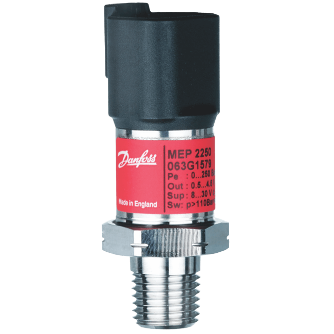
MEP 2200/MEP 2250 Electronic Pressure Switch
Brand: DanfossMEP 2200 and MEP 2250 Versions for use in mobile hydraulic applications.
- Dual output
- Output 1: Switch output
- Hysteresis 1% of full scale
- Time constant 1 Millisecond
- Output 2: Analog output
- Ratiometric or absolute voltage output
Specifications
Brand
Accuracy
- < ± 0.15 % of Full Scale/10K - Thermal Accuracy
- 1 % of Full Scale (Includes Non-Linearity, Hysteresis & Repeatability)
Ambient Temperature Range
- -40° to 125° C (-40° to 257° F)
Applications
- Cavitation, Liquid Hammer & Pressure Peaks
- Liquid Filled Systems with Changes in Flow Velocity
- Mobile Hydraulic Applications
- OEM Applications
Approvals & Certifications
- EMC Directive, 2004/108/EC
- UL 508
- EMC EN 61326-2-3 (Emission, Immunity)
BSP Connection
- G 1/4” A Male
Burst Pressure
- psi: 5801.5 to 58015 (MPa: 40 to 400, bar: 400 to 4,000)
Compensated Temperature
- -40° to 125° C (-40° to 257° F)
Connection Material
- Glass-Filled PBT 30 % GFR - Deutsch DT04-4P [Gold (Au)-Plated], Mini DIN Plug [Tin (Sn)-Plated], Deutsch DT04-3P [Tin (Sn)-Plated]
- PBT 30 % GFR Gold (Au)-Plated - M12 x 1
- Stainless Steel - M12 x 1
Consumption
- 4.5 mA - Supply Current Consumption
Delay Time
- Time Constant: 1 millisecond
Electrical Connectors
- Deutsch DT04 3-Pin
- Deutsch DT04 4-Pin
- M12 x 1 EN 60947-5-2
- Mini DIN Plug EN 175301-803-A
Electrical Contacts
- Normally Closed & Normally Open
Enclosure, Body Material
- 304 Stainless Steel
- Plastic
Environmental Protection
- IP67
Gasket Material
- Viton
Hysteresis
- 1 % of Full Scale
Load
- 2 A - Max.
- 500 mA - Max.
Load Resistance
- ≥ 10 kiloohms (Connected to 0 V)
- ≥ 5 kiloohms (Connected to 0 V) - 10-90 % Ratiometric
NPT Connection
- 1/4”-18 Female NPT
- 1/4”-18 Male NPT
- 1/8”-27 Female NPT
- 1/8”-27 Male NPT
Output
- 0-10 V - Analog Output Signal
- 0-5 V - Analog Output Signal
- 10 to 90 % Ratiometric Voltage - Additional Output
- 1-5 V - Analog Output Signal
- 1-6 V - Analog Output Signal
Output Impedence
- ≤ 90 ohms
Overpressure & Static Pressure Limits
- Overload Pressure: psi: 435 to 30,460 (kPa: 3,000 to 210,000, bar: 30 to 2,100) for with Integrated Pulse-Snubber
- Overload Pressure: psi: 435 to 43,500 (kPa: 3,000 to 300,000, bar: 30 to 3,000) without Pulse-Snubber
Pressure Cycles
- Durability, P (10 to 90 % of Full Scale): > 10 x 106 Cycles
Process Connection Material
- 630 Stainless Steel (17-4 PH)
Process Temperature
- -40° to 125° C (-40° to 257° F)
PT/PF/PS (JIS) Connection
- 1/4”-19 PT Male
RFI/EMI Protection
- 100 V/m, 26 MHz to 1 GHz - EMC Immunity RF Field (Cable < 30 metres)
- 3 V/m, 1.4 GHz to 2.7 GHz - EMC Immunity RF Field (Cable < 30 metres)
Set Point - Decreasing
- bar: 0 to 600
- kPa: 0 to 60,000
- psi: 0 to 8,702
Set Point - Increasing
- bar: 0 to 600
- kPa: 0 to 60,000
- psi: 0 to 8,702
Shock
- 100 G as Per EN 60068-2-27
Supply Voltage
- ± 36 V - over/Reverse Voltage
- 12-32 V - Polarity Protected
- 8-32 V - Polarity Protected
Switch Type
- Transistor (NPN & PNP)
System Pressure
- bar: 3,000
- kPa: 300,000
- psi: 43,511
Temperature Range
- -55° to 150° C (-67° to 302° F) - Transport Temperature
Torque
- 18 to 20 Nm (159 to 177 In/Lbs)
- 30 to 35 Nm (265 to 310 In/Lbs)
UNF/UNC Connection
- 7/16”-20 UNF Male-2A
Vibration
- Sinusoidal Vibration: 20 G, 10 to 2,000 Hz as Per EN 60068-2-6
Wetted Materials
- 630 Stainless Steel (17-4 PH)
- Mobile Hydraulic Applications
- Cavitation, Liquid Hammer & Pressure Peaks
- Liquid Filled Systems with Changes in Flow Velocity
- OEM Applications